|
The user screen
• Manually controlled output 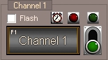 Here you can see the operating panel for output no.1. The other channels are identical in operation. Output no.1 has caption 'Channel 1' here. This heading can be changed by the user. A click to the BIG button and the output stays activated as
long as you keep the mouse button pressed down. By releasing the button the output goes to low signal again (push button function). The same function is available thru the keyboard by pressing F1 (in this example it is the F1 key, see inscription on each channel for hot-keys).
Here you can see the operating panel for output no.1. The other channels are identical in operation. Output no.1 has caption 'Channel 1' here. This heading can be changed by the user. A click to the BIG button and the output stays activated as
long as you keep the mouse button pressed down. By releasing the button the output goes to low signal again (push button function). The same function is available thru the keyboard by pressing F1 (in this example it is the F1 key, see inscription on each channel for hot-keys).
To the right of the push button there is the switch button. A click to this button lets the output stay in it's state until you click again on the switch (switch button function). The green LED always signals the state of the current output. The red LED acts as an emergency-stop. A click to the red LED and the output is turned off directly and blocked for further signals. • Random controlled output 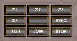 With this control panel you can activate the random generator. Z1 means that only one channel at the same time is activated randomly. Channel 1 or max. Channel 24 is randomly controlled, depending on your random-end settings in the main menu.
Z2 controls 2 channels at once randomly, Z3 therefore 3 channels and Z4 controls 4 channels at once randomly.
You can switch ON/OFF or directly switch over. The same functions are also accessible from the main menu. Use the rotary knob of the speed panel to set change intervals.
With this control panel you can activate the random generator. Z1 means that only one channel at the same time is activated randomly. Channel 1 or max. Channel 24 is randomly controlled, depending on your random-end settings in the main menu.
Z2 controls 2 channels at once randomly, Z3 therefore 3 channels and Z4 controls 4 channels at once randomly.
You can switch ON/OFF or directly switch over. The same functions are also accessible from the main menu. Use the rotary knob of the speed panel to set change intervals.
• Program controlled output 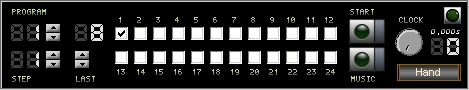 Select the wanted program number and the step-position with the arrow buttons. Activate the program with a click to the run-button. The value of the rotary knob stands for the time until the next program step occurs. The programs output status is shown via check fields 1 - 24. In the example there are already some programs ready to run.
• Change programs automatically 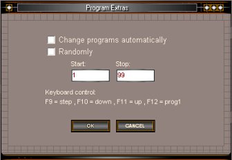 The programs can be changed also automatically, for example by sequence or randomly. If "Randomly" is selected the programs will be changed by random, otherwise the programs will be changed in sequence. The range of the programs to change can be set by Start and Stop.
It is possible to set the program to the next program, previous program or program 1 by keyboard. • Create a program Select from the main menu = > programs, = > program. The status display shows 'program mode'. Now choose the program number and the desired step. Set the check-box 1- 24 of your choice to switch channel high or low with this step, that's all. Continue this for each step of your program. The max. last program step is 99. If you are thru with your programming set the 'Last' step number. To save and exit program mode just click to the Exit button on the status display. Example: Program 1, Step 1: mark 1 Program 1, Step 2: mark 2 Program 1, ... Program 1, Step 24: mark 24 set 'Last' step to 24 and save your work with 'Exit' run the program and you see a 'walking light'! You can also edit each single program manually with a simple text editor. e.g. open the file 'prog1.txt' with your text editor. Line 1 contains the data for all 24 outputs on step 1, line 2 contains the data for step 2 and so on. A 'X' stands for ON signal and a '0' (zero) stands for OFF signal. To set channel 1 to HIGH you should write: X00000000000000000000000 . Finally if you did changes with the editor you have to set the program length via the Licht24 Pro program. • Programs - Extras Using the program mode there is a real one-push On/Off function possible! That means you can turn On/Off any channels with an external non locking key. First create a program with 2 steps. Step 1 is e.g. channel 1 Off, Step 2 is channel 2 On. The program sets the next step with every impulse so we have a On/Off function using an external non locking key. To control the program with an external button it needs to have the button connected to the joystick-port (Pin 2 + 4). That is the standard connection for the joystick-button 1 and is monitored thru Licht24 Pro when you switch on the "music-button". You should NOT connect a sound signal to the LINE-IN connector of your sound card using this feature. • Music controlled output 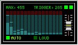 If the music-switch is pushed the interval speed becomes controlled by the music. You need to plug in a sound signal to the LINE-IN port of your sound card. Be sure to enable recording in your sound cards mixer software. The beat is filtered and a clock impulse is generated for each beat. If no program is running this signal is used to control the random impulse.
You can control the sensitiveness manually or with the automatic function. To have a good sound signal use an adjustable earphone output or AUX output, so it is easy to set the basic volume. Because every music track is different and uses different beat frequencies it can be that the filter will not achieve the best results every time. Songs with a clear beat and less interfering frequencies in lower range are ideal. • Speed settings 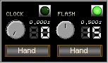 The rotary knob 'Clock' setting determines the interval time. New program or random values are set on every impulse. It is possible to control an impulse manually by pressing the 'Hand' button.
The rotary knob 'Flash' setting determines the interval of time that the outputs are working in flash mode. It is possible to control an impulse manually by pressing the 'Hand' button.
The rotary knob 'Clock' setting determines the interval time. New program or random values are set on every impulse. It is possible to control an impulse manually by pressing the 'Hand' button.
The rotary knob 'Flash' setting determines the interval of time that the outputs are working in flash mode. It is possible to control an impulse manually by pressing the 'Hand' button.
• Automatic timer controlled output 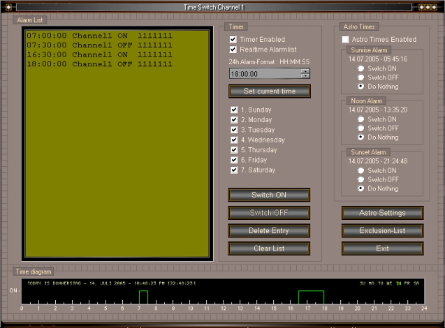
To control any outputs via the timer choose from the main menu = > Programs, = > Alarm list, = > Channel no. or simply click to the clock icon of desired control panel. The alarm list window for selected channel appears. All switching times are displayed in alphabetic order. Enter the new alarm time into the edit field, eg. 20:15:00 . Then select the days of the week that the alarm time is enabled. If you want to have an ON signal corresponding to the date/time use the 'Switch ON' button, or use the 'Switch OFF' to have an OFF signal. Every channel has a extra graphical view for the alarm list entries. If the "realtime timer" check box is checked all changes are immediately sent to the outputs in realtime. Furthermore all automatic timers are checked at program start to detect earlier ON times so the corresponding channel is set to HIGH if necessary. The outputs are switching exactly and immediately as represented in the time diagram. To erase an alarm list entry first mark the entry with a mouse click, then press 'Delete Entry' button. 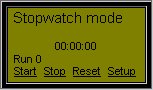 Normally all alarms are controlled via the PC system clock, but it is also possible to use a internal stop watch. The internal stop watch is especially interesting to start sequence controls only when required and independent to the system clock.
The stop watch can be controlled also witch external push buttons connected to a COM port. The buttons need to be connected to the COM port as you can see in the schematic: 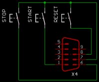
In the settings of the stop watch you can adjust a time to stop the stopwatch. The end of a sequence is defined with that time and the clock is set back to 00:00:00 again. The program is ready now for a new run. With the "Auto Start" function the stopwatch starts again automatically at 00:00:00. The sequence is working practically in an endless loop. 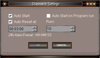 With the "Runs" setting you can intend how often an sequence will be repeated. Reaching the adjusted number of "Runs" stops the stopwatch.
By starting the stop watch manually the "Run" counter is set back to 0 again. A setting of 0 "Runs" means infinite runs. Using the stopwatch mode with active "realtime alarmlist" the programs shouldn't start at 00:00:00 because the outputs with a time of 00:00:00 are already set to HIGH at program start. Either you start your sequence times with 00:00:01 or you deactivate the "realtime alarmlist" for the corresponding output. The stop watch can be started also music controlled. With an active music button the stop watch is started with the first trigger impulse of the sound display. With this feature a program can be made for a certain song and it is started synchronously when the music begins. Astro settings: By activation of the astro times feature you can add times to the alarm list for sunrise, noon and sunset times automatically. Astro times are deleted or added automatically from/to the alarmlist daily. To calculate the times for your location you have to enter your position once at the astro settings panel. You can find the latitudes and longitudes of the worlds cities and towns at http://astro.com/atlas More information about time zones here: time zones 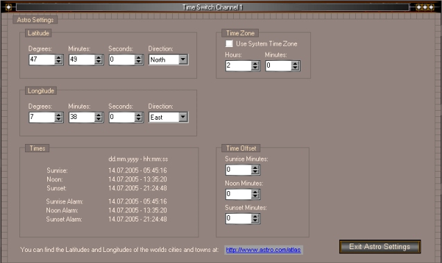
• Automatic timer - Exclusion list 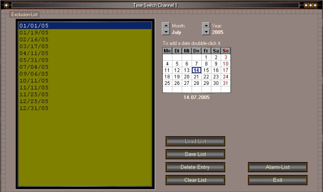 It is possible to deactivate every automatic timer on certain days using the exclusion list, e.g. holidays or days on which the alarm list is deactivated. The exclusion list can be loaded or saved. There is already a ready holiday list, just load the file "holiday_us.dat". • Input controlled output Licht24 pro supports the inputs of a Velleman K8055 USB card as well as the inputs of a bksoft 8IO card. This are 5 digital inputs and 2 analog inputs for each Velleman card, or 8 digital inputs using the bksoft 8IO. In a separate "Inputs Setup" window each of the inputs can be assigned to a output. 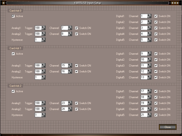
You can select between ON or OFF action. The "toggle" function changes the output state of the corresponding output, that means an input pulse sets or resets the corresponding output. For the analog inputs the trigger can be set from 0-255. Additionally there is a hysteresis function to avoid flicker on the outputs. The current measurements can be shown in a separate info display. 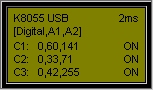 3 Velleman K8055 USB cards are supported, so max. 15 digital and 6 analog inputs can be used for the control. Or use 3 bksoft 8IO boards to have 24 digital inputs. Because of the use of inputs the range of application is extended by a variety of possibilities. Thermostats, twilight switches, limit switches, capacitive or inductive proximity switches, float switches, photoelectric beams, motion detectors, radio controlled sensors, any kind of sensors and switches can be involved to the control by using the inputs.
• Pulse Mode 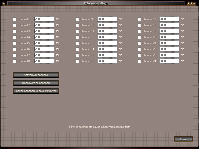
Every channel has a separate timer to realize switching off delays. Originally this function was developed to control surge relays. Meanwhile there can be set a individual time up to 49 days for every channel. The maximum interval value is of the type cardinal and therefore 4294967295 ms. 4294967295 milliseconds div 1000 = 4294967 milliseconds 4294967 seconds div 60 = 71582 minutes 71582 minutes div 60 = 1194 hours 1194 hours div 24 = 49 days 1 second = 1000 milliseconds 1 minute = 60000 milliseconds 10 minutes = 600000 milliseconds 60 minutes = 36000000 milliseconds • Data output speed 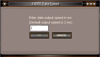
For some cards you can set the data output speed. New USB cards can process a higher data rate than serial cards. Therefore the outputs can be switched faster, that means it is possible to have more switches per second. Also a program run with a impulse rate of 0,02 seconds is now possible. To this the data output must be carried out within this time. Most USB cards have a data processing time of 1-5 milliseconds. If you don't need many switches per second you can set the data output speed to 100ms, with such a speed the data is sent to the card 10x per seconds. If you change the data output speed you should always check for a error-free function! • Sounds 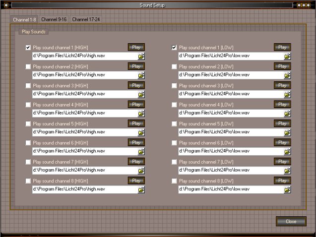
By means of individual sound output for every channel it is now possible to play arbitrary sounds on HIGH and/or LOW. Using different sounds the corresponding channel can be detected acoustically or being provided a soundtrack for. The 2 default sounds which are included with Licht24 pro can play a higher sound on HIGH as well as a lower sound on LOW (high.wav and low.wav). By the use of speech files a function can explicit be announced, eg. "light on" and "light off" and so on. Search the internet for some more nice wav files! (http://www.freesound.org) • Counter function 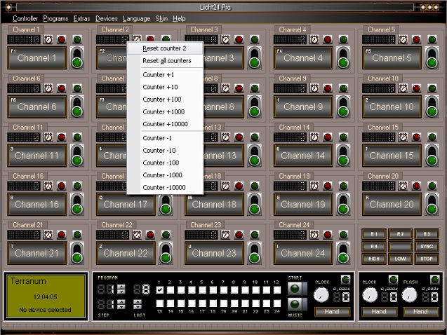
With the counter function every HIGH switch can be counted for every channel. • Skins To change the skin just click onto the application icon and select the "Available skins" entry. 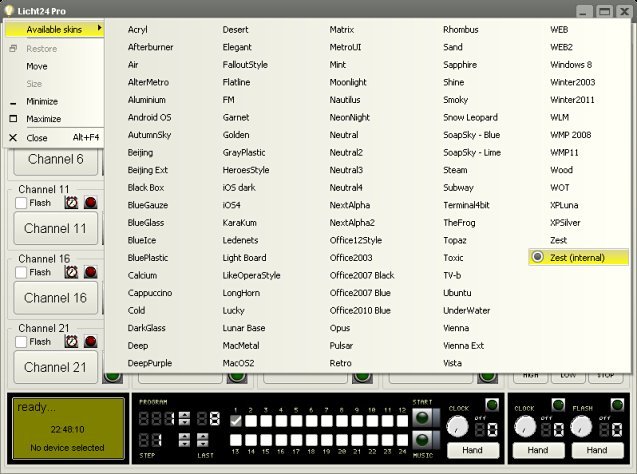
• Status - Display 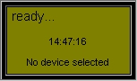 The status display shows current running program operations / functions. Additionally it shows the selected device.
| |
|
Copyright © by bksoft |